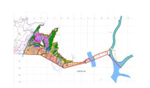
Name: Topography Survey For Reconstruction of Vital Infrastructures Damaged by Cyclone Aila in The Kingdom Of Bhutan
Name of the Client: Ingerosec/ JICA, Bhutan
Project Description: Bench Mark Installation, Topographic features survey, Profile, Road cross section, River cross section, River centerline, Drawings and Reports for Mangdechhu, Dolkhola,Jigmiling Zam, Kela Zam & Jangbi Zam Bridges.
Scope of work:
The main purpose of the Survey Works is to produce the topographic plan maps, road profiles, cross sections. These data shall be used as a reference for the road and structures design, and digital data required for the road and bridge CAD software, and establishment of the Concrete Control Points, which shall be used in construction stage.
The Works shall be executed in accordance with the terms, conditions and requirements of this Contract and under the supervision of the Engineer.
Working Area
The topographic survey area is as follows;
(1) Doklhola Bridge (Sarpang)
(2) Jigmeling zam Bridge (Sarpang)
(3) Kela zam Bridge (Tongsa)
(4) Jangbi zam Bridge (Tongsa)
(5) Mangdechhu Bridge (Tongsa)
Coordinates system and Datum level
Coordinates System and Datum Level shall be referred to WGS84 Datum of Global Positioning System (GPS). Datum Level shall be related to the available hydrological data, which will be used to analyze the high water level for the bridges along the concerned Project area.
Field survey works
The Field Survey Works shall include the installation of Bench Marks and control survey by GPS and/or closed traverse with total station and direct leveling, topographic feature survey, collection of cross sectional data and data arrangements for digital mapping, control points description and etc.
Installation of temporary control points as the reference point for the topographic survey and collection of the cross sectional data
1. The temporary control points shall be set at least 100m intervals along the existing road. As an installation conditions, from every control point, all the road features between the adjacent control points on both sides as well as the adjacent control points itself, shall be visible for the purpose of accurate traverse, center line survey, topographical survey and etc.
2. Each control point shall be a driven concrete nail at asphalt pavement edge with a painted number or to be set in an undisturbed location near the road.
Bench marks shall be buried up to 0.45m in the ground and a height of 0.05m shall remain above the ground and a flag or a signboard shall stand nearby for identification.
Bench marks shall be accompanied by a clear and intelligible monograph comprising a brief description of the location, a sketch with the distance from the nearby landmarks, photographs and 3 dimensions coordinates data.
Control traverse survey by GPS and/or by Total station
1. The control points may be surveyed by GPS Bi-frequencies Stations working in a static mode with at least 5 tracking satellites per site. The accuracy shall be confirmed by the comparison between different networks of GPS observations and will be less than 10 mm + 1 ppm. The GPS network will be linked to the GPS control points if possible.
2. It is also possible that the control points can be surveyed using Loop and/or Closed traverse method comprised of two individual Total Station team works.
3. One team shall make traverse survey to connect the Bench marks by two sets of observations for both angles and distances. The traverse shall be considered to close to GPS points. The temporary control points shall be used as the supplementary control points between permanent concrete monuments.
4. Another team shall observe all temporary control points by a closed traverse method employing with permanent concrete monuments. One set of angles and distances shall be read at each traverse station by face-left reading and face-right reading, respectively.
5. The maximum difference between the face-left and face-right readings shall not exceed twenty (20) seconds and the mean angle shall be accepted as the observed angle. Closure error of angles for the traverse shall be less than 10” * √n, where n being the number of the observation points. Accuracy of linear closure shall be less than 1/10,000.
6. Total station and data logger shall be used and raw field data shall be submitted as a digital data within one day after the observations completion. All equipments should be examined at first using time, and any defect or injury shall be reported immediately.
Vertical control survey by direct leveling
The leveling will be carried out by forward and backward round method, and shall be started from a known control point and/or be connected to another known point. Observation error between forward and backward or Closure error in connecting to a known point shall be less than 20√s mm, where s being the observation distances in km. The raw field data shall be submitted within one day after the observations completion as the digital data.
Topographic survey for the road shape and the road structure
(1) Topographic survey
Within longitudinal and cross-section of road survey, major changing points and 10m interval at each surveying point, with 1m contour lines.
(2) Road structure
Also the four corners of the structures (at the left and right carriage way edges of beginning and end of the structure) and Soil investigation positions such as boring points etc. shall be taken. For the convenient for the design work, the road center and structure shape will be taken in advance.
(3) Centerline survey for road
Beginning point, Wandue Phodrang side,(B.P), Ending point (E.P), Intersecting point (I.P)and major points for New proposed road line and Existing road line.
(4) Profile leveling for road
B.P, E.P, major points and 10m interval, including establishing temporary bench mark.
(5) Cross-section for road
25m wide from center line in both side, major changing points.
River Survey for the Bridges
River cross section survey shall be carried out at 20m intervals for the stretch of 80m on both sides of up and down stream of the planned bridge location. The required survey width shall cover the river width and 25m from each edge of bridges. In the survey, interview or observation with regard to the highest water level and normal water level shall be carried out to local habitants and residents or referring to flood marks, to indicate these data in the drawings.
More detail topographic survey shall be carried out around the planned bridge site.
Data arrangement, Mapping and Reporting
• All field observation data shall be submitted as a digital data within one day after the observations completion with brief note and necessary corrections on a printed paper.
• Calculations will be carried out independently by both the Engineer and by the Contractor to verify the results.
• All survey results including the 3-dimentional digital topographic maps shall be prepared as ASCII files and shall be compiled in AutoCAD or AutoCAD readable format (e.g. DWG or DXF format). The classification of the topographic data and the layers structure and arrangement of AutoCAD files shall be instructed by the Engineer.
• The fair drawings shall be printed. The sheet size of drawings to be submitted shall be “A3” size in an international standard. The sheet index and sheet layout shall be proposed by the Contractor and approved by the Engineer. All drawings shall be prepared based on the metric system and shall be produced in the international standards form which is commonly accepted in engineering practice.
• All control points with name and all natural and artificial features such as buildings, drainage, bridges, road/footpath, vegetation boundary, river/stream and etc shall be indicated on the topographic maps. Also, the boring points with their ground level elevation shall be indicated on the topographic maps.
• Contour lines shall be drawn in 1m intervals, and every 5m the contour line shall be indicated in a thicker line. Moreover, the spot elevation shall be indicated with its reference point on the topographic maps.
• Description of Control points which comprises of a brief description of its location, sketch with distance from nearby landmarks, photographs and 3 dimensional coordinates data, shall be indicated on the reference data to locate the Control points during the construction stage.
• All the pre-mentioned items shall not be paid separately and shall be deemed to be lump-sum item stated in the Bill of Quantities.
Materials to be submitted
The Contractor shall submit to the Engineer the following products;
1) Raw field data (field books), daily activity report.
2) Control points description.
3) Inventory of dimensions and conditions for Bridges, Culverts, Pavement and other structures.
4) Drawings
5) Reports
The contractor shall submit the survey reports, which shall contain, but not limited to, the followings:
– Photos, location map and control points network diagrams.
– General information including the survey purpose, area, period and etc.
– Mapping information such as origin coordinates, projections, scale factors and etc.
– Results (coordinates tables, accuracy tables, calculation sheets and etc.)
– Code legend for topographic survey and Layer legend for digital maps
– Survey data in an ASCII text file with one data point per record in the file.
-Digital files for all data including drawings and reports. These digital files shall be provided on CD-ROM or DVD-ROM.
Land Owners Survey: This clause shall be applied to Chanchey Bridge
Land owners and land ownership boundaries in the right of way of the planed alignment shall be investigated at actual field and the land ownership offices.
These work items shall not be paid separately and shall be deemed to be Topographic survey along the Road items stated in the Bill of Quantities. Period for this work shall be considered separately from the other survey work; therefore this work is not necessary to be included in the initial schedule of the survey work.

