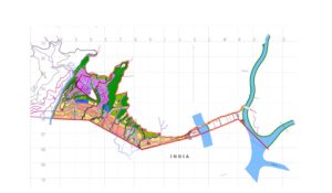
Name: Design of Mitigation Measures for Bhawanijhora Landslide area
Name Of the Client: Ministry of Works and Human Settlement, Department of Roads
Project Description: The construction of a 1.3km access road in Pasakha, Chukha dzongkhag was completed in 2019 as part of the SASEC road connectivity project. It falls under the Primary National Highway (PNH) Standard, and was implemented to improve the cross border movement between Bhutan and neighboring countries. However due to a heavy monsoon which triggered a landslide, infrastructure was damaged and as build structures both upstream and downstream were covered with debri. The objective of the project is to improve and design structures to mitigate risks posing to road user and facilities from the slide. This project intended to carry out the detailed geotechnical studies and design mitigation measures at Bhawanijhora (landslide area), Pasakha, Chukkha Dzongkhag (district).
Scope of work: The detailed scope of the works was as follows
Description of actual services provided by your staff within the assignment:
The detailed scope of the works was as follows:
Site Study and Survey Works:
Visit the landslide area to familiarize with the existing site conditions. The overall landslide area at Bhawanijhora is approximately 215 acres but scope of study area is not limited to this boundary.
Carrying out detailed engineering topographic surveys including cross sections for the study and design purposes. Establish benchmarks and reference beacons as required to prepare detailed engineering design and to enable construction quantities to be calculated with reasonable accuracy.
Desk Study:
Carry out detail review and assessment of relevant past studies/reports covering topographical maps, geological maps, land use maps, as- built structure, aerial photographs, satellite imagery and climatological records of the project area. Consult the relevant stakeholders to obtain the required information of the project area for the purpose of investigation and engineering design of mitigation structures.
Geological Investigation:
Identify, assess and prepare instability inventory maps (landslides, erosion, debris flow, scouring, toe erosion, creep, subsidence, rock fall, planar failure, wedge failure, toppling, etc.) within the study area and indicate the level of hazard posed by the instabilities. All the instabilities identified within the study area should be mapped on l :500 scales maps.
Identify, assess and prepare the material/engineering geological maps for the study areas.
Identify, assess and mark on map all water bodies (springs, creek, stream both seasonal and perennial, seepages, rivers, etc.) that have impact on the study area. (viii) Identify and assess the strength of geological materials by conducting necessary
field and laboratory tests and analysis.
Assess the correlations between the instabilities and geology (rock type, soil and deposits), topography (slopes), hydrology (rainfall, seepages, and ground water) and determine the most significant factors that are responsible for causing the instabilities.
Geophysical Investigation:
Carry out the geophysical survey using seismic refraction test (SRT) and electrical resistivity test (ERT) to understand the sub surface conditions of the landslide area (ground water table, material types, depth of the sliding plane, overburden thickness etc).
Profile line as described below:
a) Along the slope (A1) 430m b) Across the slope(A2) 500 m c) Along the slope(A3) 500 m d) Across the slope(A4) 490 m
Profile line as described below:
a) Along the slope (B1)450m
b) Across the slope(B2) 350 m
Rotary Core Drilling Investigation:
Carry out the necessary exploratory rotary core drilling works to substantiate results of geophysical investigation. (4 bore holes with 15m depth)
Carryout visual and tactile examination of each samples, describe material type (soil/rock) and maintain record of depth from the surface, elevation details and photographic records of each sample. Borehole log shall be as per relevant IS Code.
Standard Penetration Test (SPT) carried out in the boreholes where ever feasible.
Geotechnical Investigation:
Assess and characterize the engineering properties of in-situ soil and rock. (xviii) Carry out trial pitting minimum of 5 nos of 3 m depth and collect soil samples for laboratory test in order to determine the bulk density, moisture content, grain size distribution, cohesion, angle of internal friction, plasticity indices, permeability etc.
Conduct soil tests e.g. Gradation test, Atterberg limits, Field Density, Unit weight, moisture content and the Direct Shear Box Tests as per relevant IS or any internationally accepted standards.
Assess and compute safe bearing capacity for design of appropriate engineering structures based on the finding of in-situ and laboratory tests results conducted on the soil samples.
Assess and determine the strength and depth of the soil forming the slope and most likely worst-case ground water and soil moisture conditions.
Assess location and extend of weak layers and cavities, if any, below the surface.
Carry out the slope stability analysis for design. The slope stability analysis of soil and rock slopes should include: Depth and configuration of the failures.
Carry out the soil/rock mass classification, geotechnical strength of soil/rock materials and the configuration of soil/rock strata, including basic geological indicators (e.g dip direction/dip) and other features such as fissures, faults, discontinuities in the case ofrocks and, density, cohesion and friction angle and other characteristics in the case of soils.
Assess worst-case groundwater table, and surface/subsurface soil moisture conditions.
Assess the debris flow in the worst-case scenario of climatic condition with surface/subsurface soil conditions and groundwater.
Compute factor of safety for the slope with recommended mitigation action plan. (xxviii) Assess probable settlement and probable differential settlement of the foundation.
Assess the likely construction difficulties, risks to the slopes, structures, people involved during construction of the structures and chart out the mitigation action plan to nullify the risks.
Collect the meteorological and hydrological data of the project area and analyse it prior to design of mitigation structures.
Compute the maximum probable discharge based on rainfall-runoff analysis. (xxxii) Determine the probable floods for various return periods based on flood frequency analysis and design the hydraulic structures based on the maximum probable flood discharge (Minimum 25 years return period).
Assess and determine the extent and depth of scour for the foundation hydraulic structures.
Conceptual Design for Counter/Mitigation Measure Structures
Based on the findings of detailed geotechnical investigation, the consultant shall recommend and submit three alternative conceptual designs for countermeasure structures along with probable estimate.
The proposed countermeasures can be combination of various mitigation techniques as appropriate.
The client shall select most appropriate countermeasure structures recommended by consultant during presentation of midterm progress report.
Phase 2: Detailed design of mitigation measures/counter measures
Detailed Design of Counter Mitigation Measure Structure
Carrying out the detail design work on the selected option above;
Preparing standard drawings. The drawings should be done in an appropriate style and the scales suitably fixed so that they are easily readable at site or workshop by naked eye. Except for the general views, the drawings should preferably be made to the scale of 1:50 and for showing minute details to 1:20/ 1: 10 / 1:5 where necessary;
All drawings should be made to paper size – ISO A3;
All drawing dimensions shall be in metric system (i.e. meter, em and mm); (xli) Preparing of Bill of Quantity (BoQ). The BoQ should be explicit covering all items of work. It should be as exhaustive as possible to avoid changes, additions, deletions and substitutions during execution and therefore the undesired disputes and claims;
Preparing rate analysis and cost estimate for all civil works. The cost estimates should be appropriately worked out to indicate the approximate cost of the structures. It should be accompanied by analysis of rates where necessary. The rate analysis and the cost estimate should be treated as highly confidential; Prepare a detailed Technical Specifications for all items of work taking into consideration the relevant Code of Practices and the advancement in technology;
Prepare Quality Assurance Plan (QAP) for civil works;
Prepare construction methodology and schedule for civil work.

